


Temperature Controller Project
For years I've desired and needed a way to control the firings of my pottery. Simple ceramic cones may be good at getting clay and glazes to maturity, but doesn't allow for firing many types of glazes, such as crystalline glazes, or the soaking and slow cool down for certain glaze effects. There is also the aspect of having to manually ensure the kiln is heated slowly during ramp up and ramp down so as not to damage pots. A controller will solve all these problems. Given I've got two kilns I fire, a dedicated controller would leave one kiln doing without, so a stand-alone kiln controller would service both kilns for the price of a single controller.

Pottery is a hobby for me, not a livelihood. As such, I can't spend the amounts of money typical for stand-alone kiln controllers. I found a temperature controller kit produced by a small company, EmbeddedRF, which would solve my need at a 1/3 to 1/4 the price of a stand-alone, off-the-shelf, controller. A good descriptive page for the controller, and it's applications, is here. I talked with the proprietor, an engineer by trade, and found this kit to be the answer to my needs.
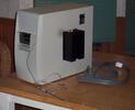
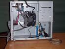
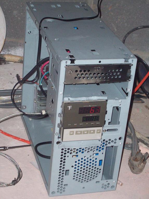
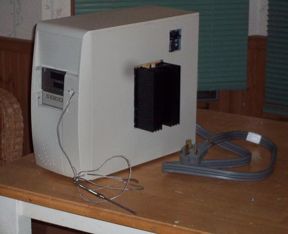
The kit includes the electronics and temperature probe, computer interface software, but not the case, electrical connectors, cords, etc. The picture, above right, is the controller installed into a PC case.
I decided to use a PC case because I was familiar with using them; there was no decent knockout box at the local Home Depot which would fit the controller; plus they are expensive compared to some PC cases.
This is a temporary page here on the website of the Zen Center of Georgia (which I run). Since I've used a page from the site as a template for this, some of the art and links are Zen related. I will be keeping this page up for only a few months.
The Temperature Controller Project
Problem:I need to control the temperature of my kiln for firing pottery.Solution:
embeddedrf.com's E5AX temperature controller kitNeeded Items:
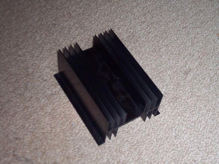
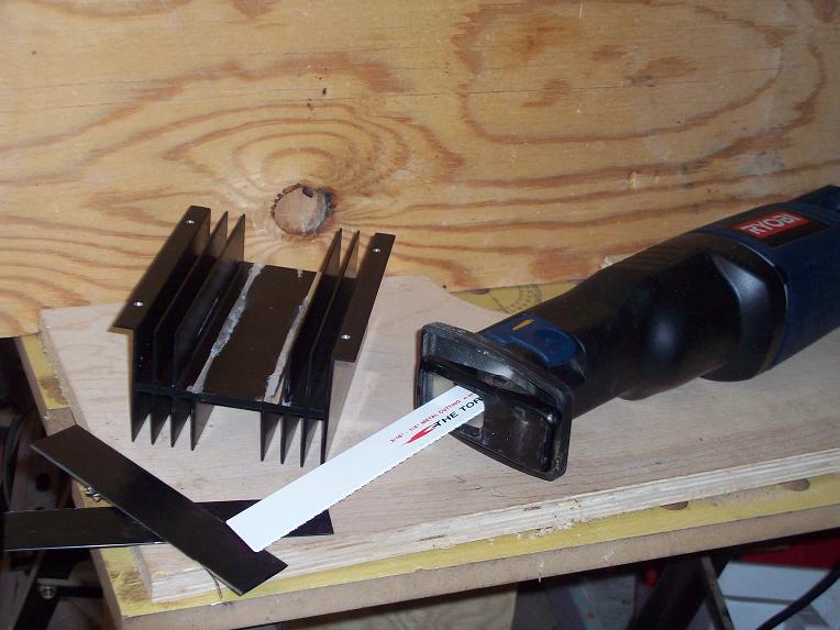
E5AX temp controller kit

	E5AX controller
	90 Amp SSR
	K- thermocouple
	RS422/485 to USB converter

Case	- Small PC Case
Heatsink   - 1.2 deg C per watt or less
Heatsink paste/grease
Pigtail - 240V /50A cord/plug (NEMA 10-50)
240V NEMA 10-50 receptacle
120V PC Fan (for heatsink)
120V receptable + enclosure   (optional)
120V plug/cord (for fan)
240/50A  circuit breaker  (optional)   to be used as on off switch
Nuts, bolts
Wiring 6/10/14 gauge
High amperage connectors

Offset strips (Al) 	(optional)
CAT5 cable, 2 ft	(optional)
DB9 female and male connectors (optional)
Steps:
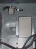
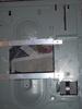
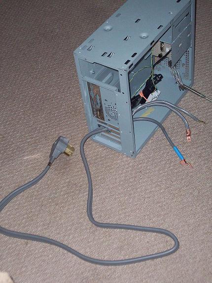
| 1. Cut hole to fit into case front, then install E5AX unit. 2. Install cord/plug into case |
 |
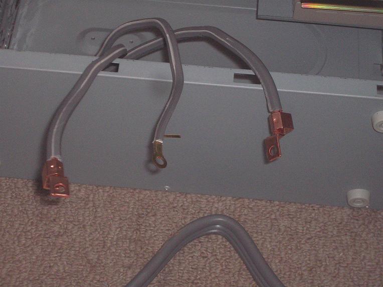
| 3. Attach connectors to pigtails. These connectors were a gift from god! I picked up a cheap ($6) 50 amp circuit breaker that would work well as both extra circuit breaker protection and as an on off switch. Home breakers have an input connection, in the form of a slot, on the back of the breaker. They are designed so the power conductor in the breaker box will slide into this slot when it is installed in the breaker box. These conductors slid into the input slot perfectly. |
 |
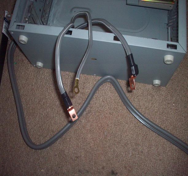 |
4. Insulate exposed breaker wiring inputs (pigtails). The disadvantage of these connectors is they form an exposed electrical conductor, even when slotted into the back of the breaker. For safety reasons, I used heat shrink tubing to cover as much of the exposed copper surface as possible. You can see this in the picture to the left. |
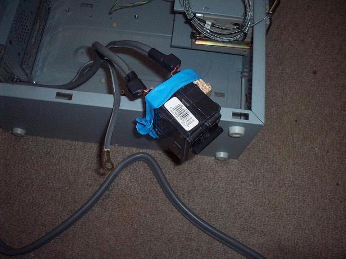
| 5. Insert connectors into breaker. 6. Test cord and breaker for voltage and on/off capability. Voltage checked out fine and the breaker works well as an on/off switch. I wrapped some more (blue) heatshrink tubing around the breaker to further cover exposed conductors. I had hoped to then heat the tubing and shrink it around the breaker. It turns out the tubing I used only shrinks laterally, not longitudinally. *sigh* |
 |

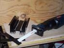
| 10. Mark hole in plastic side cover for heatsink. 11. Mark hole in plastic side cover for heatsink. |
 |
|
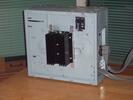
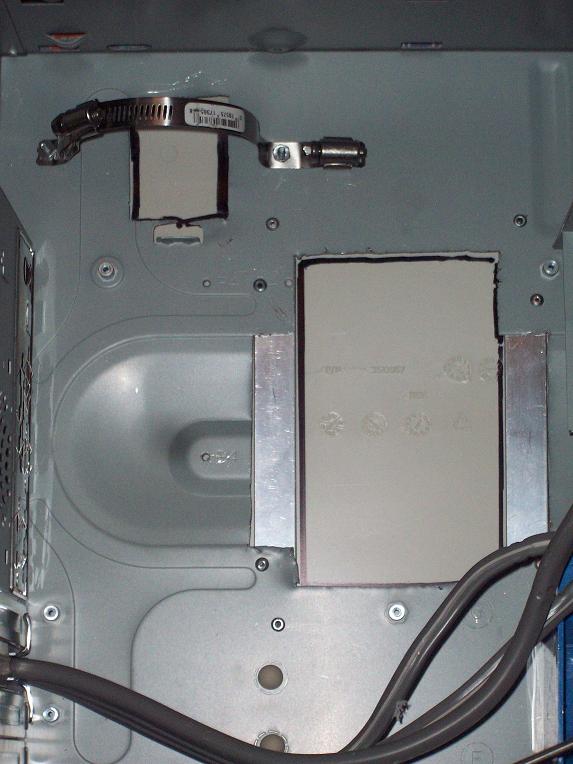
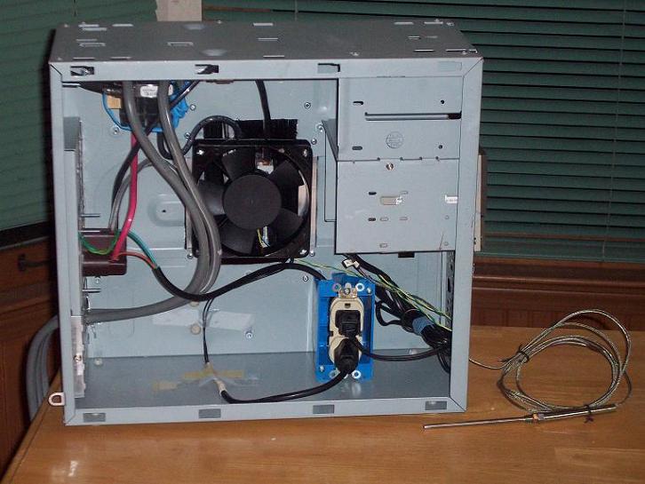
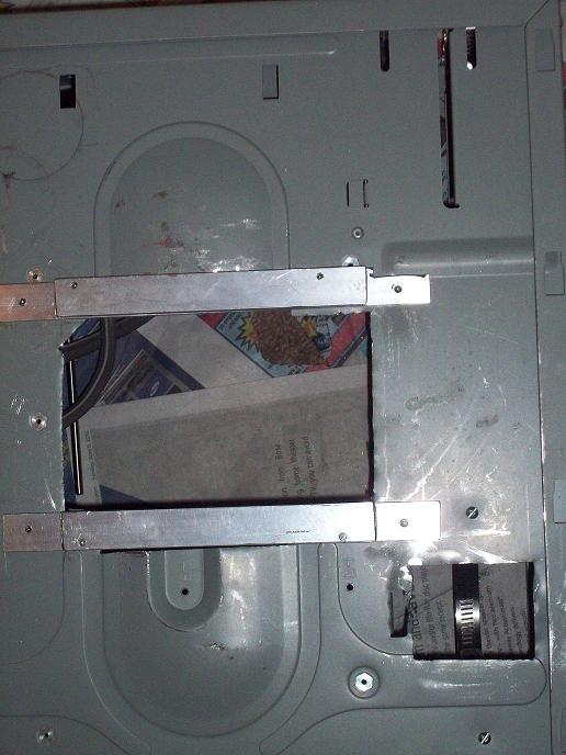
13. Install/attach breaker 14. Drill holes and attach 120V enclosure 15. Attach 120V receptacle to enclosure w/ wiring unattached at supply end 16. Wire heatsink to 240V wiring 17. Install fan and heatsink along w/ Al offset strips 17a Ensure no air gaps 18. Connect 120V plug to fan 19. Mark and cut hole for 240V NEMA 10-50 receptacle 20. Attach 10-50 receptacle. |
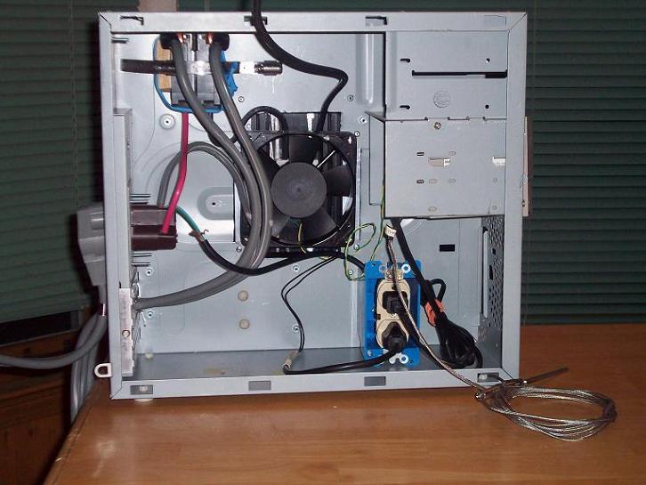

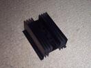
- It's not apparent from the pictures, but the heatsink is held in place by four 1.5 inch metal screws (#8-32). The screws go through holes in the fan, from the inside of the case, through the aluminum strips, into threaded holes on the heatsink.
| 21. Test fan (120V household line). I worked as expected. 22. Plug fan into 120V receptacle 23. Test temperature measuring of E5AX, at room temperature and using boiling water (and 120V household line). Room temperature measured was exactly the same as the home thermostat. Boiling water measured 210 degrees Fahrenheit. I checked the boiling point of water at 1010 ft elevation (which is the altitude where I live). It is about 210.23 degrees Fahrenheit. |
 |
 |
24. Wire 240V Neutral line from the pigtail to 10-50 outlet neutral, with neutral wire to 120V receptacle. 25. Wire 240V Hot wire from breaker output (A) to 10-50 outlet hot(A). Use Red wiring. 26. Wire 240V Hot wire from breaker output (B) to SSR 240 input gated line. Splice the 120V hot wire to the B wire output on breaker. Use Black Wiring. |
- 27. Wire 240V output gated line, to 10-50 outlet other hot (B). Use Black Wiring.
All high amperage wiring is 6 gauge. Typically you can get away with smaller gauge wire when you have small runs, like inside a case, but I went for a low wiring load.
28. Double check all wiring.
The 120V circuit powers the E5AX unit and fan. The logic behind wiring the 120V circuit into the B side of the 240 was this: If I find an application where I want to control temperature application later on, I can create a 120V to 10-50 NEMA adapter, with the neutral coming in on the neutral line and the hot coming in on the B (switched) line. A similar adapter could be made for the output recepticle of this box (10-50 to 120V out). With both these adapters in place, the temperature controller would easily work with a 120V application.
| 29. Construct RS422 cable for inside the case. This cable will plug into the db9 communications port on the E5AX and connect to the back of the case, so I could plug the RS422/485 to USB converter directly into it and interface with my laptop. |
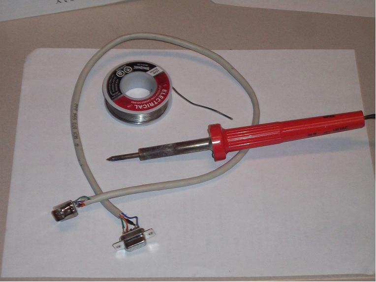 |
- 30. Attach DB9 wiring, for RS485/422 output, to case backing (from E5AX).
31. Double check all wiring.
|
32. Install software on Laptop. 33. Check entire system's ability to program the controller and it's ability to control the kiln. The software installation took two tries, for both the USB driver and the SKC controller software, but it's an old laptop, what can I say. Once on the computer, I had to scan for the correct port. Once it found the controller, all was again right with the world. It programmed the controller with no problem. I toted the entire setup down to the kilns in the basement, hooking everything up the way it would be used in an actual firing. It worked like a dream. It did work a little different than I expected. I expected it to work like a thermostat, coming on until it reached the current target temperature, then shutting off. What it did was pulse on and off, with the on part of the duty cycle longer the further below the target temperature it was, shortening as it got closer, but not completely off until about 10 degs above target. Such a clever little PID controller. One big surprise was that the heatsink stayed dead cool the whole time. *Thumbs UP!* I love it when a plan comes to together. I suspect it will heat a bit at the top of the firing schedule, where the duty cycle will be more heavily weighted to the "on" part of the cycle to keep the temp rising. Still, I beleive it would be utterly capable of dissipating all heat produced by the SSR even with if the fan fails. |


| 34. Setup Microsoft Outlook to talk with my ISP. So far, I've got it to recieve mail, but not send mail. The SKC software will send me warnings via email if I have Outlook setup correctly. All I've tried hasn't allowed me to get Outlook talking correctly with my gmail acct. *sigh* 35. Drill holes in both kilns for the thermocouple. |
| To be done: 36. Celebrate! |

This is a video describing the basic construction process.
|
Awakening to this present instant, we realize the infinite is in the finite of each moment. |